Wooden Boat People
By McKenzieDriftBoat.com
Questions about Trapper Design -- Boatbuilding Class
Well . . . I've gone and done it. Last spring, I got approval to start a boatbuilding class at our local school. I've got half of our High School and one middle-schooler in the class (this totals 8 kids). We're going to build a Trapper and a Zs Drifter Pram. Super fun stuff.
So far, we've been working on reading Roger's chapters on general building process, and the Trapper. All students have created their own card-stock hull model of the Trapper (and floated them down the irrigation ditch) and created a one-fourth scale layout board of each station for the Trapper.
Which brings me to my first two questions of many on the Trapper:
1: Have any of you that have built from the book experienced problems with the location (fore-aft) of station 2? When we modeled the boat in Autodesk Inventor, there was no way to make a fair curve and we had to re-locate station 2.
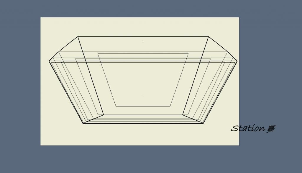
2: I've attached a drawing of the layout for all 7 stations. Amazingly, all 8 students matched up nearly exactly to this cad version. As you can see, the side frame on one station (#3) is not similar to the rest. It seems as if there should be a relatively consistent angle to the side panel, or at least there should be a relatively smooth transition from (unidirectional) to any changes in side angle. One student surmised that since the chine log is to be ripped with a consistent bevel between the bottom edge and face, that it would make sense that the side panels would be at a consistant angle.
I sure appreciate any feedback and experience any of you may have had in building the Trapper. I promised the students that I would report back to the class any wisdom you might all have.
Thanks a bunch
Tom
CTE Teacher
Glenwood, WA
Views: 558
Replies to This Discussion
-
Permalink Reply by Tom Anderson on
-
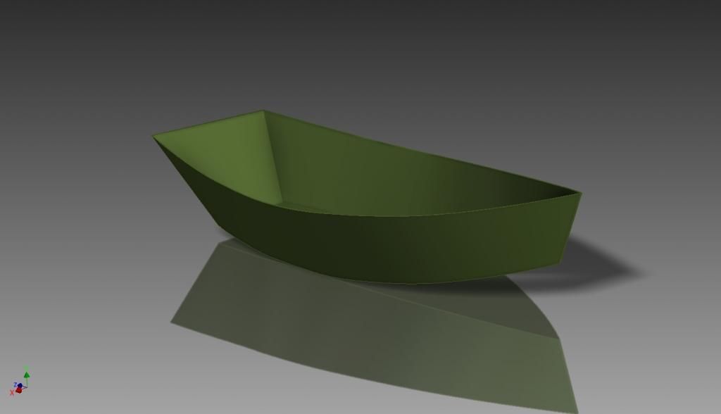
. . . btw, here is the shell (no panel thickness here, just a study of the shape) the students modeled in Inventor:
-
-
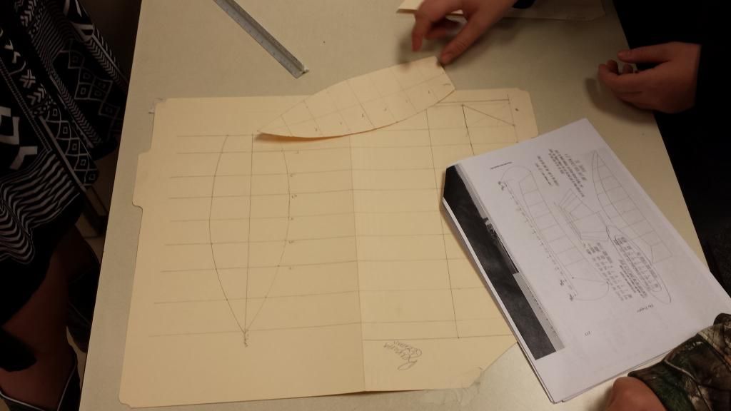
and the models in process: (Roger gave me permission for the photocopies of sections of his book . . .thanks so much Roger).
-
Permalink Reply by craig curtis on
-
I am currently rebuilding my trapper that was built to the boat builders handbook. the only way I could get the chine in were to steam bend otherwise they have a lot of force on them and snap easily. On the outside bevel it is easier to do it once installed to make them flat across the bottom. I won't curve off the last two stations if you plan on putting a motor on it, hand to plane. You may want to talk with Cyrus at Ray's River Dories about their design its wider and more stable.
-
Permalink Reply by Roger Fletcher on
-
Tom -
Kudos to you and your class for undertaking the project(s).
A little background -- I recovered the lines to the Trapper in 1998 in the darkened barn of Frank Wheeler, the boat's owner. Helping me were Dave Helfrich, Leroy Pruit, Frank Wheeler and Bill Girsch. To correctly capture the lines, I put the boat in an imaginary box, which required the boat to be square to the baseline of the boat. I then committed the lines to paper, built a model to confirm the lines, and then Dave Z built the first-off to test the efficacy of the lines. Since I am tactile by nature, basically computer illiterate re CADs, and wanting to maintain the traditional method of drift boat building, these lines (to my knowledge) have not been put to the test of CAD precision, preferring instead to loft the lines and test their efficacy full size. I find that my eye is a much better judge of trueness/fairness than my rule or protractor. As I fussed over the lines of all the boats I have “recovered,” my mentor and dear friend, Dynamite Payson said to me: “Roger, these are boats. They are not airplanes.”
Since these are boats and not airplanes, and early builders tended to simplify things, the angles represented in the plans are averages. For example, the flare of each rib rises off the bottom frame at a slightly different angle. The bevel cuts on the chine represent the mid-point average of the angles off vertical. It would be a challenge to cut bevels consistent to the angle of each frame. The Rogue builders typically didn't worry about the chine. They simply cut them square and the chine sits 90 degrees to side panel. The McKenzie chines, on the other hand, are typically beveled, primarily to keep water from standing, settling and seeping in along the chine's seam to the panel.
The bevels to the side frames that receive the side panels also vary as you move fore to aft, as the panel raps around the boat. These bevels are intended to assure a nice and flush fit of the panel to the frame. Interestingly, on many boats (Trapper included) this bevel is slightly different at the sheer of the boat and at the chine of the boat. To the early builders simplicity reigned. The two angles were averaged, and that average angle is used for the length of the side frame.
If indeed frame # 2 is an abberation (and it appears that is the case if the CAD is correct, a fault of my failing eyes and hands at the drafting table), the way I and my predecessors would solve the problem is to correct it as you build it. In other words, craft the centermost frame first, dry fit it, and then craft each frame alternately fore and aft to the lines in the plans. Your eye and some measurements will tell you, when you get to frame # 2 if indeed there is a problem.
Again, kudos to you, Tom, for affording your class a unique opportunity. My wife and I had the pleasure of attending a launch of two boats built by a freshman class in S Bristol, Maine, last spring. It was a great experience for them, and they stood a few inches taller in emotional height than they did at the beginning.
Stay in touch.
p.s. By the way, if the class would like a scaled set of plans, please advise. I would gladly ship a set gratis for the kids. They are much easier to work from.
-
-
Hello Roger . . .
Thanks for taking the time to reply . . . much appreciated. I have read your fantastic book, and had a great conversation with the kids about how you went about recovering the lines of the Trapper. They thought it was pretty neat. So . . . I meant no offense whatsoever by questioning any accuracy. I, like you, love the traditional ways. I am a big fan of hand-drawn lines even for architecture. But at the same time I want these kids to be developing other employable skills in todays advanced world. I think building traditional wood boats, but working in the modern planning and design means is a great mix.
I tell kids in all my classes regularly that all we're doing with any machines, computers, tools, sanders, and finishes is trying to please the amazing and discerning human eye. And . . . sometimes we need to 'fudge' things from what all our technology says is right to satisfy those eyes.
I will definitely keep yo posted, and we were about to put together a purchase order for a book (so I can take mine back home), a set of Trapper Plans, and a set of Zs drifter plans.
Tom
-
Permalink Reply by Dave Z on
-
Tom,
Second Kudos- I wish I had a class that did a project like this in my school years!
I designed the Z drifter pram and can answer any questions you might have. For what it's worth, I designed that boat solely from paper models,trying t o fit it in the confines of my material availability. I wanted a boat with maximum material utilization and no wasted wood. I think I suceeded. I later then did draw up the frames in AutoCAD, just for reference on my shop wall, where they probably do still hang today. Roger put hand-to-paper and drew up the plans made available for sale.
door is open tom, you let me know anythign you need on the pram or the trapper for that matter.
Dave
-
-
Much thanks Dave.
We are going to attempt both boats, so you may be busy answering questions. The Trapper will be built as a class project and will get sold/auctioned/raffled at the end of the school year (assuming it's completed!). One student said that he and his Dad would like to build one to keep (so they will be paying for those materials), but after discussing the different designs available, they have settled on your drifter pram.
Should be fun.
© 2026 Created by Randy Dersham.
Powered by
![]()